
A wearable can produce a clean waveform on the engineering bench and still fail to deliver repeatable measurements in production. The electronics may power on, Bluetooth may connect, and the application may display data, yet signal amplitude, baseline stability, noise, or channel consistency can shift once normal variation enters the build.
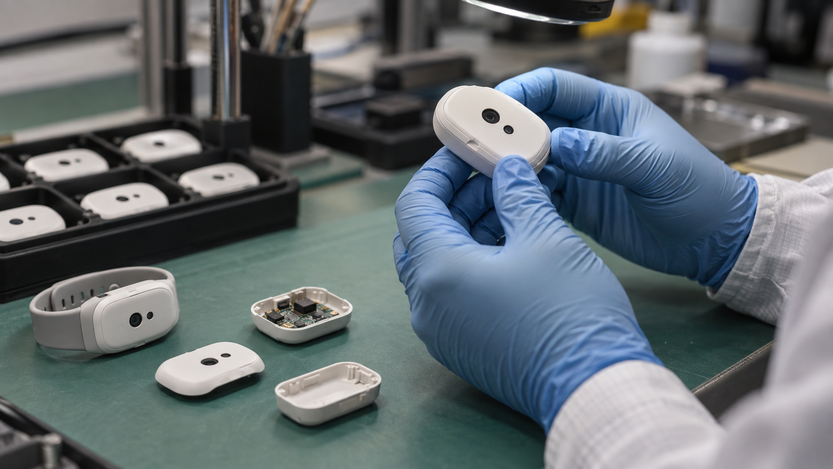
That gap became visible during the transfer of an anonymized home-use rehabilitation wearable from prototype assembly to controlled production. The system combined body-worn bioelectrical sensing modules, motion sensors, disposable textile electrodes, embedded firmware, wireless communication, charging hardware, molded housings, and consumer-ready packaging. Its signals were measured at microvolt scale, so apparently minor changes in contact, pressure, materials, routing, or configuration could affect the final result.
The engineering challenge was not to prove that the sensing IC worked. It was to reproduce a trustworthy measurement across assembled devices, electrode lots, operators, firmware versions, and use conditions. That distinction is central to any EEG, EMG, ECG, PPG, or multimodal wearable moving toward pilot production.
Accuracy Belongs to the Complete Measurement Chain
Wearable teams often begin with the most visible specifications: analog-front-end noise, ADC resolution, sampling rate, sensor sensitivity, LED output, MCU performance, or algorithm accuracy. These are necessary inputs, but none describes the performance of the finished product on a human body.
The real measurement chain starts at the body interface and continues through the electrode or optical path, mechanical stack, protection network, analog front end, conversion, firmware configuration, data transport, signal processing, and application. A change at any point can alter what the algorithm receives.
For optical sensing, the effective signal path includes LED wavelength and drive current, photodiode response, optical geometry, window transmission, skin pressure, ambient-light rejection, and motion between the device and the body. For bioelectrical sensing, it includes electrode material, conductive media, contact area, pressure, skin impedance, cable movement, common-mode behavior, grounding strategy, analog protection, and mechanical retention.
Motion sensing adds another dependency. Enclosure orientation and attachment compliance influence whether an IMU represents body motion or movement of the device relative to the body.
This is why a functional test is not an accuracy test. A unit can boot, pair, charge, stream data, and display a plausible waveform while still having incorrect gain, excessive noise, weak common-mode rejection, unstable baseline, or mismatched channels.
Finished-device requirements should therefore describe measurable system behavior. Depending on the intended use, these may include amplitude accuracy, input-referred noise, baseline drift, frequency response, common-mode rejection, channel-to-channel consistency, saturation recovery, packet loss, and synchronization between biosignal and motion data.
The limits should reflect the product claim and expected use environment, not merely the nominal capability of a component.
.png?width=1774&height=887&name=ChatGPT%20Image%202026%E5%B9%B48%E6%9C%8814%E6%97%A5%2017_22_33%20(1).png)
The Body Interface Changes the Electrical System
For skin-contact wearables, the electrode is not a passive accessory. It participates directly in the measurement circuit. Electrode material, conductive gel or fabric, contact area, adhesive behavior, pressure, hydration, sweat, hair, motion, and wear time all influence the impedance and stability seen by the analog front end.
Disposable textile electrodes created one of the most consequential supply decisions in the rehabilitation wearable. Several constructions appeared similar in a drawing, but they behaved differently during assembly, storage, peeling, and skin contact.
Evaluation therefore went beyond nominal resistance. The team compared conductive-area consistency, gel coverage, liner release, adhesive stability, edge lift, handling during kit assembly, packaging compatibility, and the risk of changes after storage.
A paper-backed construction initially appeared attractive because it was familiar and economical. However, the backing and release behavior introduced avoidable shelf-life and contamination risks. The production direction used a controlled release liner, defined gel coverage, anti-stick protection, and individual barrier packaging.
This was not a packaging preference. It was a signal-quality and product-life decision.
The lesson is broader than one electrode design. Any consumable or skin-contact part that affects signal capture needs functional specifications and change control. Useful controls can include:
- Impedance or resistance under defined conditions
- Conductive-area dimensions
- Gel weight, thickness, and coverage
- Adhesive peel behavior
- Liner release force
- Packaging seal performance
- Accelerated-aging results
Visual inspection alone cannot confirm electrical behavior.
The same principle applies to reusable dry electrodes, conductive textiles, optical windows, acoustic membranes, adhesives, and skin-contact foams. These parts may sit outside the schematic, but their influence on body-to-sensor coupling makes them engineering-controlled elements of the measurement chain.
Mechanical Tolerances Become Signal Tolerances
Mechanical design determines how consistently the sensing interface is held against the body. Enclosure flatness, foam thickness, textile stretch, adhesive compression, connector position, PCB seating, strap tension, and molded-part tolerances can all change contact pressure or permit relative motion.
Too little pressure can increase impedance, create intermittent contact, or allow ambient light into an optical path. Too much pressure can cause discomfort, alter local blood flow, deform a gasket, or make fit dependent on the user.
Uneven pressure is equally problematic because it can make one channel behave differently from another even when both channels use the same electronics.
Connector and cable behavior also matter. Movement at a cable entry can couple artifact into high-impedance bioelectrical channels. A contact that is electrically acceptable when stationary may become intermittent after repeated insertion, textile flexing, or enclosure movement.
Contact compression, mating alignment, strain relief, and retention should be tested in the assembled wearing configuration rather than only as separate component checks. The hardware was intentionally similar, but the application needed to know which data stream came from each side.
A swapped assignment did not create an obvious hardware failure. It created plausible but incorrectly labeled motion data. The production flow therefore treated pairing order, module identity, firmware configuration, and final kit verification as controlled quality characteristics.
Correct physical placement, orientation, channel mapping, and device identity are part of measurement integrity. A wearable can capture an accurate signal from the wrong location and still produce the wrong conclusion.
Firmware Configuration Can Create Hardware-Like Errors
The same assembled PCBA can behave like a different instrument after a configuration change. Gain, sampling rate, filter cutoffs, reference selection, channel enablement, lead-off behavior, bias settings, calibration coefficients, timestamp handling, and packet format all influence the delivered data.
Many firmware errors are difficult to detect by visual review because the waveform still looks believable.
An incorrect gain value can scale amplitude without changing waveform shape. A filter change can suppress clinically or functionally relevant content while making the display appear cleaner. A channel-map error can exchange body locations. A synchronization defect can separate motion artifacts from the movement that caused them, weakening downstream analysis.
Production controls should therefore verify more than a firmware version string.
The released build needs a controlled configuration, repeatable programming method, verification after flashing, and a record linking each unit to the installed firmware and calibration data. Test software, fixture firmware, device firmware, and analysis limits should be versioned together so that a later investigation can reproduce the conditions under which a unit passed.
Device pairing deserves the same discipline. When a kit contains multiple wireless modules, the manufacturing process should define how identities are created, bound, labeled, checked, and recovered after rework.
The final verification should confirm that the application receives the correct device, channel, and side assignment—not only that a Bluetooth connection exists.
.png?width=1774&height=887&name=ChatGPT%20Image%202026%E5%B9%B48%E6%9C%8814%E6%97%A5%2017_22_33%20(2).png)
Calibration Must Be Designed as a Production Operation
Calibration is often treated as an engineering adjustment added near the end of development. In production, it becomes a process with fixtures, reference equipment, software, operator instructions, limits, records, cycle time, maintenance, and failure handling.
Three activities should remain distinct.
Design validation confirms that the product architecture can meet its performance requirements. Factory calibration corrects predictable unit-to-unit variation where correction is technically justified. User setup or baseline adjustment accounts for fit or individual physiology.
If user setup is routinely compensating for parts or assembly differences, the production process still has an unresolved control problem.
Calibration also cannot repair information that was never captured. It may correct a stable gain or offset, but it cannot reliably compensate for intermittent electrode lift, uncontrolled optical attenuation, a moving connector, clipped inputs, or random noise from poor grounding.
When calibration coefficients become unusually large or unstable, the right response is often to investigate the signal path rather than broaden the accepted range.
Cycle time makes these decisions commercially important. The production test flow for the rehabilitation wearable used an automated biosignal analyzer and required approximately eight minutes per unit for the core sequence.
At 1,000 units, eight minutes represents more than 133 station-hours before setup, loading, retest, maintenance, or investigation is included. That does not make the test excessive. It makes test time a capacity and cost input that must be planned before launch.
Early planning allows teams to add accessible test points, stable mechanical datums, controlled compression, suitable connectors, automated data capture, parallel fixtures, or a reduced production screen correlated with broader validation.
Late planning leaves the factory dependent on manual positioning and engineering judgment, which is difficult to scale and difficult to audit.
Production Testing Should Measure the Product Claim
Power-on, charging, Bluetooth connection, and sensor communication are useful manufacturing checks, but they do not demonstrate biosignal performance.
A production test strategy should detect the failures that would invalidate the measurement while remaining fast and stable enough for routine factory use.
The implemented core sequence evaluated signal-amplitude accuracy, baseline stability, mains-frequency interference rejection at 50 Hz, and frequency response. Noise and common-mode rejection were covered in the broader validation framework, together with system-level behavior and representative simulated signals.
Functional checks for pairing, charging, and kit completeness were connected to the same unit history.
During the first controlled build of 50 units, one amplitude result fell outside the expected distribution. Because the system stored channel-level results rather than only a pass/fail flag, the investigation could isolate the behavior to one acquisition channel.
That prevented a single outlier from becoming either an unexplained batch rejection or an incorrectly accepted unit.
This is the value of testing a distribution instead of celebrating a golden sample. A few carefully assembled prototypes show that the design can work. A multi-unit, multi-lot build starts to reveal how electrode batches, PCB assembly, molded parts, connectors, adhesives, textile components, firmware, fixtures, and operators interact.
Test limits require equal care. Limits set too close to the nominal value can reject good products because of normal measurement uncertainty. Limits set too wide can allow units that no longer support the product claim.
The team should understand the repeatability of the analyzer and fixture, correlation between engineering and factory stations, environmental sensitivity, cable and grounding effects, and the guard band between the production limit and the true product requirement.
A test station that cannot reproduce its own result is not measuring product variation reliably. Reference-equipment calibration, fixture maintenance, contact-life tracking, software validation, and periodic correlation checks belong in the production plan.
For health or medical applications, factory screening also remains separate from formal verification, risk management, and any testing required by applicable regulations or standards.
The Pilot Build Should Expose Variation
A pilot should challenge assumptions that were protected during prototype work.
A high shipment yield may conceal repeated connector reseating, electrode replacement, firmware reflashing, mechanical adjustment, or test retries. First-pass yield, failure categories, retest rate, rework time, and measurement distributions provide a more honest view of process repeatability.
The pilot plan should deliberately include production-intent materials, normal operators, released work instructions, actual fixtures, representative supplier lots, and expected packaging.
It should also include realistic use states: worn movement, charging, reconnecting after signal loss, low battery, repeated electrode replacement, and wireless recovery. A wearable that is stable only when placed carefully on a quiet bench has not yet demonstrated production readiness.
Multiple lots matter because supplier and process variation often appears outside the characteristics listed on a purchasing description.
Two conductive textiles may share nominal resistance but differ in coating uniformity, edge fraying, compression response, or aging. Two adhesives may share thickness but differ after sweat exposure or repeated flexing. Two molded parts may meet drawing dimensions but distribute pressure differently after assembly.
Production-intent builds make these interactions visible before volume magnifies them.
Supplier substitutions should follow the same logic. Form, fit, and a generic datasheet match are not sufficient when the part participates in signal capture.
Critical-to-signal characteristics need incoming controls, lot records, and approval rules. Alternate sources are most valuable when qualified before a shortage or quality escape forces an urgent decision.
Traceability Makes Failures Diagnosable
Traceability is often reduced to printing a serial number. For a biosignal wearable, the serial number is useful only if it connects the finished device to the information needed to explain its behavior.
The production record should link raw test results and calibration data to:
- PCBA and assembly lots
- Critical sensing components
- Electrode or textile batches
- Adhesive and mechanical revisions
- Device firmware
- Test-software versions
- Fixtures and test stations
- Test timestamps
- Calibration and rework history
A multi-module kit should also record the binding relationship between modules and the final configuration delivered to the user.
This history changes the response to a failure. Without it, a noisy field return triggers broad speculation about the user, algorithm, supplier, and factory.
With it, the team can compare affected units, identify common lots or versions, reproduce the original test state, contain the relevant population, and avoid unnecessary rework of unaffected inventory.
Raw values matter as much as pass/fail status. A slow drift within the accepted range may show that a material or fixture is changing before failures occur.
Trend review can reveal channel imbalance, supplier-lot shifts, increasing contact resistance, or a test station moving away from its reference. Traceability is therefore not only a recall tool. It is a process-control and continuous-improvement tool.
What Wearable Teams Should Define Before Scaling
Before releasing a biosignal wearable to pilot or volume production, the team should have clear answers to the following questions.
- What measurement claim must the finished product support, under which wearing and environmental conditions?
- Which electrical, optical, mechanical, material, and firmware variables can change that measurement?
- Which characteristics will be prevented by design, controlled through sourcing, measured during validation, calibrated, or screened on every unit?
- Are electrode, optical, textile, adhesive, connector, and enclosure specifications tied to functional performance rather than appearance alone?
- Has the system been evaluated across production-intent units, normal operators, and more than one critical material or component lot?
- Can the factory verify firmware, configuration, pairing, channel mapping, and kit identity after assembly and rework?
- Does each serial number connect to raw results, critical lots, revisions, software, firmware, fixtures, and calibration history?
If these answers are incomplete, adding more prototypes may not reduce the real risk.
The next useful step is usually to make the hidden interfaces measurable and convert engineering knowledge into specifications, fixtures, records, and change controls.
From Accurate Prototypes to Repeatable Products
The anonymized wearable ultimately moved from early builds to several hundred delivered systems. The most durable outputs were not limited to the shipped hardware.
The project also produced reusable biosignal test methods, a controlled electrode supply route, clearer pairing and configuration controls, and a traceability model that could support later volume expansion.
The central lesson is straightforward. Biosignal accuracy is not created by one sensor, one algorithm, or one successful prototype. It emerges from the complete interaction between the body interface, electronics, mechanics, firmware, calibration, production process, and supply chain.
Wearable startups and established device teams reduce scale-up risk when they define that system early.
Practical control comes from assigning each significant variable to a deliberate response: robust design, supplier specification, incoming inspection, factory measurement, justified calibration, or a clear stop-ship limit.
Anything left unassigned usually returns later as inconsistent data, rework, or field investigation.
.png)