
The decisions that feel flexible during prototyping become expensive when calibration RF performance compliance and supplier variation meet the production line.
An optical health wearable had already completed a 20-unit prototype build when the first shipped batch from a 250-unit pilot run began producing weaker sensor signals. The product used a multi-wavelength near-infrared sensing system built around four infrared LEDs, a photodiode, an optical analog front end, BLE, battery charging, and power management, all on a PCBA measuring roughly 30 millimeters square. There were plenty of plausible suspects: LED variation, firmware, analog configuration, sealing, assembly alignment, or a mechanical stack-up that had moved the sensor farther from the skin.
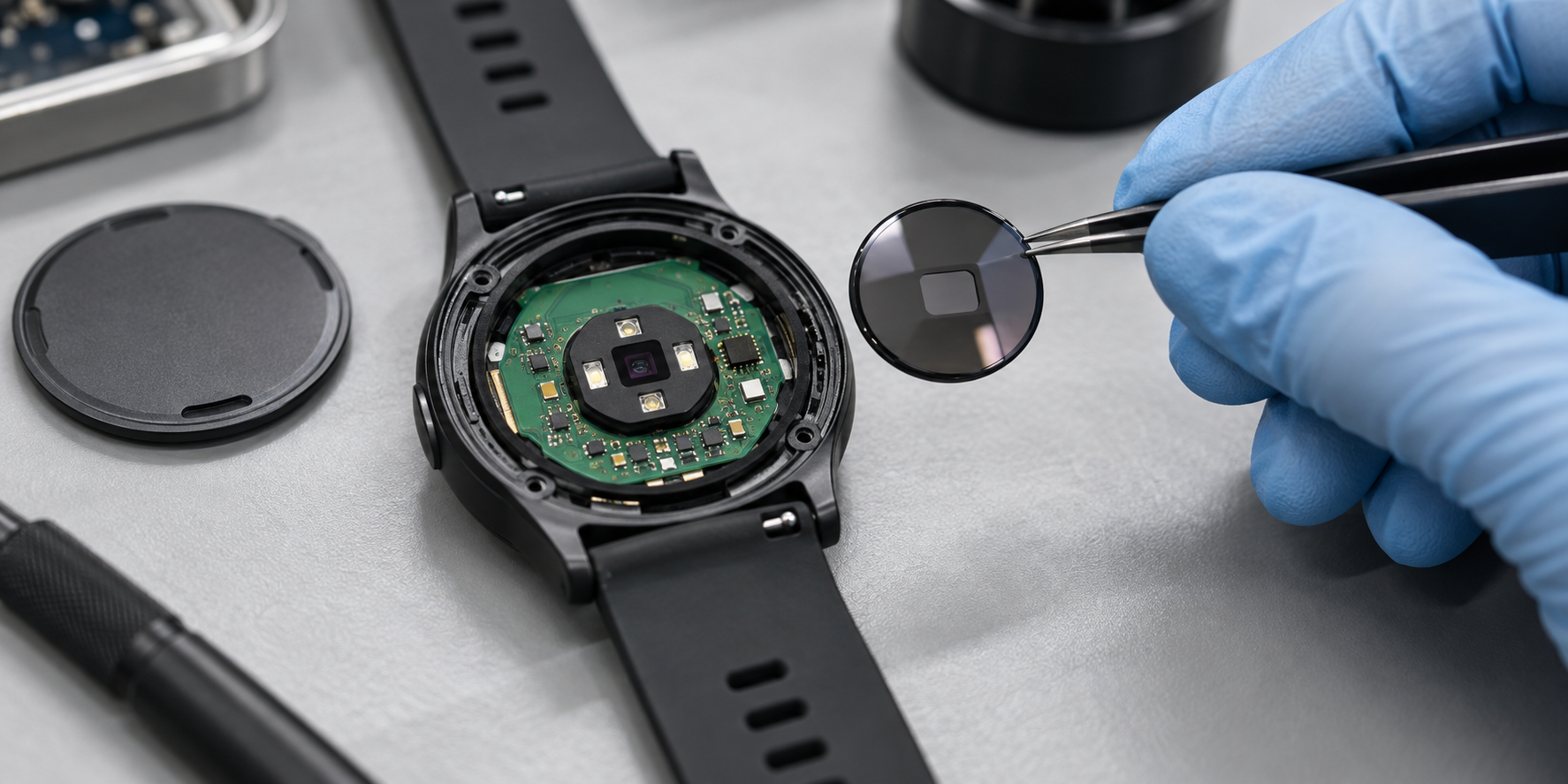
The team eventually ran a controlled comparison using the same device with optical windows from two production batches. The older window produced significantly stronger signals. The newer one still looked clear, but its supplier had changed the coating process, and the part no longer met the required near-infrared transmittance at the higher end of the sensor’s operating range. The remaining pilot units were held while the team defined wavelength-specific limits, required batch-level test reports, rebuilt the validation process, developed alternate suppliers, and prepared incoming inspection.
Nobody had chosen the wrong photodiode. A part treated as mechanical packaging had changed the physics of the product. This is where wearable programs usually become expensive. The sensor, MCU, radio, battery, and enclosure may all work in isolation while the interfaces between them remain uncontrolled. The optical window changes the signal. The enclosure and battery change the antenna. Assembly pressure changes electrode contact. Calibration changes line capacity. A protection-board substitution changes storage behavior. A prototype proves that a design can work under controlled conditions. Production asks whether it can keep working after variation enters the system.
The sensor is the signal path
Sensor selection is often run as a component comparison. Teams review noise density, current consumption, package size, sampling rate, unit price, availability, and SDK quality. Those inputs matter, but they do not tell you whether the assembled product will produce a trustworthy measurement on a moving human. For PPG, the effective sensor includes the LED spectrum, drive current, optical geometry, window material, coating, skin pressure, ambient-light rejection, photodiode response, analog-front-end range, and movement between those elements. For ECG or EMG, it includes electrode material, contact area, pressure, sweat, contact impedance, common-mode behavior, analog protection, and the mechanical system holding the electrode against the body. Even an IMU is coupled to its surroundings: mounting angle, adhesive compliance, enclosure flex, and movement between the rigid electronics and the body all change what the algorithm receives.
Our view is that a sensor should not be considered selected until the production-intent signal path has been tested as a system. A development board can prove that the component works, but it cannot validate an optical window, electrode stack, gasket, textile interface, strap, adhesive, or assembly tolerance that does not exist in the test setup. We would rather see a spread of imperfect production-intent units assembled across multiple material and component lots than a handful of golden samples built from one carefully controlled set of parts. Golden samples show what expert attention can make work. A multi-lot build begins to show the distribution the factory will have to manage.
When a nominally mechanical part participates in the transfer function, it needs a specification tied to that function. “Clear” was not an adequate specification for the optical window; near-infrared transmittance was. The same logic applies to electrode impedance under defined pressure, adhesive thickness, sensor orientation, compression force, alignment, and every other interface that changes what the product measures. If a part can change the signal, it belongs in the sensing architecture rather than being dismissed as packaging.
.png?width=1250&height=625&name=(1).png)
Calibration is a production process
Most wearable teams underinvest in calibration because development hides its true cost. An engineer can tighten a strap, reposition an electrode, change LED current, reject an unusual unit, rerun a baseline, or adjust a threshold. On a production line, every one of those interventions becomes a fixture, reference instrument, software workflow, operator instruction, test limit, data record, and block of cycle time. Factory calibration can remove device-to-device gain and offset. Temperature compensation can correct predictable thermal behavior. A user baseline can normalize physiology or fit. These methods solve different problems, and using them interchangeably creates bad products. User calibration should normalize the human, not conceal uncontrolled factory variation.
The economics become visible quickly. In one medical wearable program, the complete flow for a finished kit included module assembly, BLE pairing, signal testing, simulated-use testing, garment matching, packaging, and labeling. Each kit took about 30 minutes to assemble, pair, test, and package. At a hypothetical volume of 3,000 kits, adding five minutes of per-unit calibration would create another 250 direct labor-hours before accounting for retesting, fixture maintenance, operator training, reference-equipment checks, or investigation of borderline results.
That is not an argument against per-unit calibration. It is an argument for deciding before the enclosure and factory flow are frozen. Calibration may require mechanical datums, controlled compression, optical access, test contacts, or a fixture capable of separating device variation from fixture variation. A process that depends on an operator finding the correct position by feel is not production calibration. It is skilled manual assembly with an instrument attached. The record also needs to connect each unit to its raw measurement, reference value, coefficients, relevant component lots, fixture version, test software, firmware, station, and timestamp. Without that history, a field drift complaint becomes an argument about whether the sensor changed, the user changed, or the factory wrote a bad coefficient.
Buy the edge plumbing and build the insight
The pressure to add edge AI arrives early. An MCU with an NPU promises privacy, lower radio traffic, faster response, and a stronger product story. Sometimes it is the right architecture. Just as often, it is selected before the team has a stable signal or a representative dataset. Our default for a first-generation wearable is to buy the silicon, inference runtime, optimized kernels, RTOS, and commodity algorithms, then build the interpretation that creates defensible product value. Standard step counting, routine activity classification, common gesture detection, and conventional filtering rarely justify owning an entire edge stack. A novel physiological inference or a proprietary combination of signals may.
Machine learning cannot recreate information that never reached the ADC. It cannot recover a signal blocked by an optical coating, clipped by the analog front end, lost during a sensor dropout, or corrupted because an electrode lifted from the skin. During EVT, a conventional filter, threshold, state machine, or DSP pipeline is often more useful than a larger model because it exposes the underlying signal quality and helps generate labeled data. The useful metric later is not TOPS. It is energy per useful decision: how much radio traffic, latency, or cloud cost the local computation removes relative to the memory, wake frequency, power spikes, model-update infrastructure, and validation burden it introduces.
The RTOS choice should be made with the same discipline. Bare metal is reasonable when the state space is genuinely small and stable. FreeRTOS is often practical when a team wants explicit tasking and a narrow kernel inside a mature semiconductor ecosystem; its tickless-idle mode can stop the periodic tick while no application task is ready to execute. Zephyr becomes more attractive when its integrated Bluetooth stack and power-management framework replace enough custom infrastructure to justify the larger configuration surface. Neither platform produces low power automatically.
Battery life is usually lost in the paths that were absent from the original spreadsheet. The phone is unavailable, so the radio keeps searching. A sensor transaction fails, so a retry task wakes the MCU every few seconds. Storage is nearly full, an update is interrupted, or the charger repeatedly enters and leaves a valid state. Those paths need the same attention as normal operation. Firmware should expose why the system woke, how long it stayed awake, which task blocked sleep, how often the radio retried, and what caused the last reset. A low sleep-current number is not a battery-life result if the device rarely remains asleep.
.png?width=1250&height=625&name=(2).png)
Lock the antenna before industrial design
The antenna is a mechanical component that happens to be reviewed by the RF engineer. Its performance depends on board outline, ground plane, keep-out area, battery position, display, nearby metal, enclosure resin, coating, cable routing, strap, wearing position, and the user’s body. Waiting until the enclosure looks finished to choose the antenna architecture is one of the easiest ways to create a late redesign. Wearable antenna options commonly include PCB traces, chip antennas, flexible antennas, and LDS structures, but each option moves cost and risk into a different part of the product.
The apparent BOM trade-off can be misleading. At the time of writing, representative 2.4 GHz chip antennas were listed by Mouser at approximately $0.28 to $0.78 at 1,000-unit quantities, while one Taoglas adhesive flex antenna with a 100-millimeter cable and IPEX connector was listed at $2.68 at the same quantity. These are not functionally interchangeable parts, and distributor pricing is not a production quotation, but the comparison shows why a purchasing spreadsheet can push a team toward the wrong conclusion. A PCB trace antenna has almost no direct component cost, yet it consumes board edge and constrains ground geometry, battery placement, and enclosure layout. The “free” antenna can become the expensive option if it enlarges the board or forces a mechanical revision. A flex antenna may cost several dollars while preserving placement freedom during early development.
LDS moves the trade-off again. It allows a conductive structure to be formed directly on injection-molded plastic and can use complex three-dimensional housing geometry, but it turns resin choice, molding, laser activation, metallization, tooling, and enclosure yield into RF variables. There is no useful generic LDS unit price without the geometry, material, production process, and volume. It can be an elegant high-volume answer, but it is a poor late-stage escape route for an industrial design that was frozen without RF input.
Whichever architecture wins, it needs to be tuned and validated on production-intent hardware with the actual battery, enclosure, coating, strap, charger, cable routing, and nearby metal. It also needs to be tested while worn rather than only on an open board. In the United States, the FCC defines a portable device as a transmitting device generally used with its radiating structure within 20 centimeters of the user’s body. Whether routine RF-exposure evaluation or SAR testing is required depends on factors including frequency, available time-averaged power, separation, operating configuration, and the applicable exemption criteria. That analysis belongs in the architecture phase because antenna position, output power, and assumed use conditions are not cheap to change after design freeze.
Treat compliance as architecture
Compliance is not paperwork performed after DVT. It is an external test of the product architecture at the point when that architecture is becoming expensive to change. A radiated-emissions failure can reopen grounding, clocks, PCB layout, shielding, cables, charging behavior, enclosure seams, and firmware operating modes. An RF-exposure problem can reopen antenna placement, output power, duty cycle, or the assumed distance between the radiator and the body. The lab fee is visible, but the larger loss is usually the board spin, mechanical revision, replacement samples, retest queue, and company burn accumulated while the design is reopened.
An FCC-certified module reduces one category of radio work; it does not certify the finished wearable. FCC module-integration guidance still places conditions on the host manufacturer, including permitted antennas, operating conditions, RF-exposure configuration, labeling, integration instructions, and compliance with rules not covered by the module grant. Using a module outside its approved conditions can require further evaluation or filing.
Bluetooth qualification is a separate obligation. The Bluetooth SIG states that all Bluetooth products must complete the qualification process before they are sold or distributed, and that a supplier or another member company cannot qualify a company’s finished product on its behalf. Effective March 1, 2026, the full product qualification fee for an Adopter member is $12,000. That amount should not be treated as a universal total certification budget, but it is a real line item that frequently disappears from an early hardware plan.
The visible fees are still rarely the largest risk. A company burning $150,000 per month that loses four weeks to redesign has consumed another $150,000 before paying for new boards, mechanical samples, expedited freight, or retesting. The correct calculation uses the company’s actual burn rate, but the conclusion is the same: a compliance failure is a schedule event rather than merely a laboratory expense. Pre-compliance should therefore use production-intent hardware and representative firmware, exercising the highest realistic radio duty cycle, active charging, fast clocks, sensor streaming, storage writes, displays, motors, and every cable or accessory that may ship. A chamber is an expensive place to discover that the charging cable is an antenna.
Use the pilot to expose variation
A pilot is not a small version of mass production. It is an experiment designed to expose variation while the team can still afford to respond. Final yield alone can hide an unstable process. A line may eventually pass nearly every unit through sorting, adjustment, reflashing, rework, and operator knowledge. First-pass yield, failure distribution, rework time, and the causes behind each failure tell you whether the process is actually repeatable.
One smart-textile wearable program later moved into an order of more than 3,000 complete units plus additional textile subassemblies. After field deployment, a significant percentage of devices from a later battery batch would not charge, and some died immediately after being disconnected from USB. The electronics module had not changed. The investigation traced the problem to a MOSFET on the battery protection board with higher self-discharge current than the earlier part. Cross-testing showed that the same electronics worked with one battery batch and failed with the other. Hundreds of returned devices were eventually shipped back for battery replacement and functional recovery. The public case study does not disclose the failure percentage, current difference, or storage duration, so those values should not be estimated.
That failure is why “3.7 V lithium-polymer battery” is not a production specification. The cell, protection IC, MOSFET, connector, wire, quiescent behavior, protection thresholds, storage state of charge, assembly process, and supplier change controls can all affect field performance. The same principle applies to optical coatings, adhesives, LEDs, pogo pins, magnets, plastics, and surface treatments. A purchasing description can sound familiar while remaining behaviorally incomplete.
Production testing also needs to measure the product claim rather than merely confirm that the electronics power on. In another medical wearable program, factory testing covered signal-amplitude accuracy, baseline stability, noise, common-mode rejection, simulated body-signal response, BLE pairing, charging reliability, and kit-level traceability. The process required specialized bio-signal equipment, automated scripts, and a documented transfer of the development validation workflow into factory execution.
When a failed device returns from the field, its serial number should connect it to the PCB and assembly lot, battery and protection-board lot, sensor or LED lot, optical window or textile batch, mechanical revision, adhesive lot, firmware, calibration record, test station, fixture version, and result. A serial number without production history is decoration. The purpose of the pilot is not to demonstrate that the factory can eventually produce a shipment. It is to determine whether the process can reproduce the intended product without relying on the engineers and operators who already know all of its undocumented exceptions. Do not optimize the pilot to look successful. Design it to make failure legible.
The decisions teams regret
Wearable teams rarely regret defining calibration too early, reserving too much antenna keep-out, or testing too many material lots. They regret approving a sensor before validating the complete signal path. They regret freezing the enclosure before the antenna. They regret selecting an NPU before collecting representative data, starting formal compliance before pre-compliance, and allowing a new material or battery lot into production without a test capable of detecting the change.
Every postponed decision narrows the next one. A layout adjustment during EVT becomes an enclosure revision during DVT. An incoming inspection becomes a field-return investigation. A supplier deviation becomes a cross-border repair program. Decisions that appear flexible during prototyping become coupled to tooling, fixtures, inventory, certifications, firmware, and delivery commitments once production begins.
The founder’s job is not to eliminate variation. Bodies vary. Contact pressure changes. Batteries age. Suppliers update processes. Users wear products differently. Radio environments remain unpredictable. The job is to decide which variation will be prevented through design, constrained through sourcing, measured at the factory, calibrated out, handled by firmware, or used to stop a unit from shipping.
A prototype proves that the physics can work. A pilot proves that the process can reproduce it. Production proves whether the specifications, suppliers, fixtures, firmware, and change controls can keep reproducing it after the original engineering team stops watching every unit.

.png)