Capacitors are commonly configured for frequency filters and as decouplers in electrical circuits. To serve the different functions, different types of capacitors are used. To support these needs, many types of capacitor symbols are designed for circuit diagrams, with different symbols expressing different capacitors. Some of the few most common symbols will be discussed below.
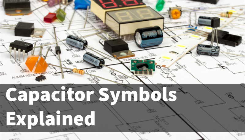
The graphical symbols of capacitors vividly express the structure of the component: two parallel lines signify the two plates where the dielectric is present within the capacitors, and two fine lines perpendicular to each of them represent their connection to the circuit wires.
The several types of capacitors to be discussed are:
1. Basic Capacitor or Non-polar Capacitor
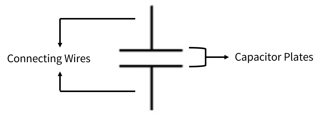
This is the most commonly used symbol of capacitors. The symbol shows the indication where a capacitor is positioned in simple circuits, where the type of the capacitor and its polarity is not necessarily indicated.
The capacitor symbol shown is the basic symbol of universal capacitors but is specifically used for non-polar capacitors such as film and ceramic capacitors. Non-polar capacitors have neither positive nor negative poles. Generally, the capacitance of these capacitors is relatively small. An example of these non-polar capacitors is the 104 capacitor.
2. Polar Capacitor
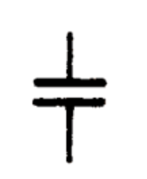
The following icon is the symbol of a polar capacitor, which means there are both positive and negative poles present in the component. These types of capacitors have a relatively higher capacitance and are generally electrolytic capacitors. The annotation for the positive pole is essential for the soldering process, as the two poles should be correctly distinguished during the placement to function.
a. UK (GB) and China Standard
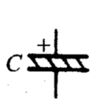
 The capacitor symbol with both flat plates is the one commonly used in China(i.e: your supplier) and is specified by the UK (GB) standard. On the other hand, the capacitor symbol with an arched plate is used as the US standard.
b. US Standard
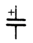
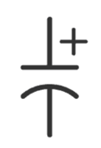 The "+" sign in the symbol indicates the location of the capacitor’s anode. With this marking, we can deduce that the other side of the capacitor holds the cathode (negative pin), and hence no further marking, i.e. minus sign, is needed.
c. International Electronic Standard
3. Variable Capacitor
a. Tuning Variable Capacitor
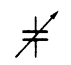
The symbol shows the basic type of variable capacitor, that is, the tuning capacitor. This type of variable capacitor’s top (i.e., where the arrowhead lies) indicates its rotor plate, while the lower part indicates the stator plate. The arrows in the graphical symbols show the variability of the capacitance, for the convenience of circuit analysis.
Variable capacitors allow the control of their capacitance through mechanical and electrical methods. These are usually done by changing their plates and dielectric configurations.
b. Ganged Variable Capacitor
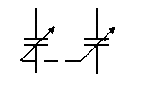
As for the ganged variable capacitors (dual-ganged capacitors or multi-ganged capacitors), a dotted line connecting the arrow ends is added to show the connection between the capacitors. The dotted line shows the interlocking of various stator plates (namely the isochronous node).
Simply explained, a dual-ganged capacitor is set up by connecting 2 capacitors together through a long shaft. The shaft is then rotated to control both of the capacitors' capacitance together. In a multi-ganged capacitor, a similar setup will be configured with more capacitors.
c. Trimmer Capacitor or Preset Capacitor

The main difference between the variable capacitor and trimmer capacitor symbols lies in the line passing through the capacitor. The variable capacitor has an arrowhead going through it, while the trimmer capacitor has a T-shaped line going through.
These preset capacitors are usually made up of multilayered parallel layers, which are set up to increase the capacitance of the component.
Mastering these types of capacitor symbols makes it easy to understand the characteristics of various capacitors in the process of viewing the circuit diagram.
.png)
.png)
.png)
.png)