During the quoting process, we will ask if you require functional testing for your project. There are many ways to do this, but to do so efficiently, having specialized test tooling (sometimes called a "test jig") is a must. In this article, we'll discuss creating test tools and some ways to do this effectively.
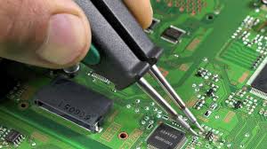
During the SMT process, some testing for the projects are done to check the integrity of the boards and make sure all of the components were placed properly. An automated optical inspection (AOI) is done, but this won't check if there are functional issues with the boards. In NexPCB's process, this is done in our local workshop as a separate step after the SMT. To create these tools, there are some steps to take to make sure that they are designed well.
1. DETERMINE THE FUNCTIONAL TEST OF PCBA
In order to create a specialized tool, the first step is to decide on what needs to be tested and what are the acceptance criteria. Some typical tests include power supply testing, port/interface testing, IC module I/O testing, and other special tests specific to the board. Once these criteria are defined, you can move on to the next step.
2. Determine the shape and process of the test tool
The next step is to define what configuration of the tooling will be able to test the needed functions. The actual shape of the tool depends heavily on the shape of the product and how many test points there are. This design must also be able to firmly hold in place the pressboard, carrier board(s) and any other modules that are needed to complete the testing. The positioning on the pressure/carrier plate must be very precise lead positioning must be very accurate so that the device being tested isn't damaged due to the test. The pressure application mechanism also needs to be very smooth as not to apply sudden pressure on the boards.
To hold this test subject in place, a box is normally designed that aids in alignment and keeps things from moving when they're not supposed to. This should be designed in such a way where the board that needs to be tested can easily be placed into the test box with a minimum of effort. There also needs to be clear, accurate keys so that the boards are always placed in the correct orientation.
It's easiest to think of this through some examples. Below are some examples of the various parts to take into account.
Test tooling:
Here is a picture of a typical testing jib with the press handle, press plate, leads and testing box all clearly visible.
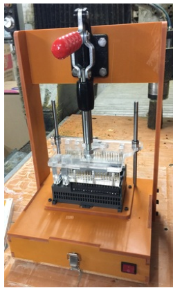
The devices that has been through PCBA is placed on the carrier board through the pressure plate. The test leads are them pressed down to connect to the carrier plate with the thimble below. The thimble fixed in the upper part of the test tool box and connected to the perforations on the plate. The bottom of the thimble connects to the external test equipment.
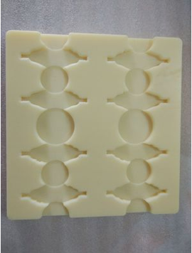
Fixtures tooling:
Make a carrier plate that fits with the PCBA to hold the PCBA.
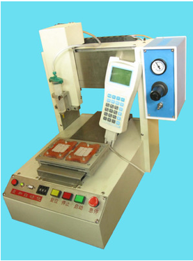
Equipment tooling:
This is an example of the professional equipment that can then be connected to the testing jig.
3. Gather Required information for making test tools
To make the test tool, a minimum of the Gerber file(s) and physical samples are required. If physical samples are not available, 3D files can also be used. There is always a risk in this in that testing the jig is essential to making sure it's correct, so without a physical model, it's difficult to do proper testing.
4. Material SELECTION
There are many decisions to be made for the testing jig, but selection of the probes and test plate materials are two of the most important. We'll discuss these two decisions below.
Test probe selection:
The selection of the test tool needle has the largest relationship with the cost of the test tool. The most common test tooling comes from Mainland China, Taiwan, Hong Kong, Germany, the US and Japan.
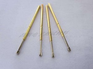
The quality of the test probe is mainly reflected in the diameter accuracy of the material, plating, spring, casing, and the manufacturing process. Speaking with relation to the Mainland China-sourced probes, many of these are made with imported materials are made of imported materials, so provided that a reputable producer is selected, the accuracy of needles and sleeves is similar to that of Taiwan and Hong Kong. Non-Chinese probes are slightly better but generally have little impact on the quality of testing. The quality of springs and coatings is much better than that of Chinese sourced probes, so this will impact longevity. Taiwan and Hong Kong produce slightly better probes as well.
The main reason is the difference in the level of technology. The poor anti-wear coating of domestic Chinese probe coatings is easy to peel off. If the production time of the test tool and the number of test times exceeds 150,000 times, it is more appropriate to use non-Chinese products. There is certainly a trade-off in cost, so this needs to be balanced. At present, the domestic Chinese production level and technology have gradually improved
and many agents prefer to use domestically produced needles. If the test requirements and the number of tests are not high, it is recommended to use domestic Chinese probes. The quality of the probe is mainly related to the number of tests in the manufacture of the test tool and whether the contact is good, so for prototyping, pilot run and small production runs, the quality is sufficient.
Test plate selection:
The plates used in the test tools are generally acrylic (organic glass), epoxy resin plates, or other similar materials. Ordinarily, if probes diameter is more than 1.00 mm the plates will made of plexiglass due to cost. 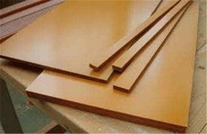 Because plexiglass is transparent, it's easy to check the test tools for problems. It also tends to be fairly soft, so there is more forgiveness with the probe drilling size. The challenge is that ordinary plexiglass tends to melt and break the drill bit when drilling when the drill hole diameter is less than 0.8mm. Generally, the epoxy resin plate is used when the hole diameter is less than 1mm. It is easier to drill the correct sized holes. Its toughness and rigidity are good but the price is higher. The epoxy board does not swell or shrink, so it's very important that the drill bit and probe diameter be exact. If the drill hole diameter is inaccurate, it will cause looseness between the probe bushing and the hole. Epoxy resin is also opaque, so if the jig has a problem, it is difficult to track down the issue. If the test density is very high need, it's also better to use epoxy for the board. The selection of the plate and the accuracy of the drilling play a key role in the accuracy of the entire test tool.
5. Precautions for making test tools
In addition to some of the tips above, some other points should be noted:
- The testing box needs to have enough space for wiring and for installing the proper testing devices (if they are mounted in the jig.
- Space should be reserved for any Fiber, MIC, SPK or SIM card simulations if they will be needed during the testing.
- The location of the testing interface should be designed as not to interfere with the physical operation of the jig
- The testing toolbox should be used to lock the main fixture and/or buckle and for parts to facilitate replacement of parts during maintenance.
- If the test tool isn't working due to broken needles, then the jig can continue to be used with simple needle replacement. However, if the test toolbox is damaged and can't be repaired, the jig must be rebuilt.
6. Summary
The PCBA test tool can greatly improve the efficiency and effectiveness of doing functional testing. NexPCB can help you design a test jig for your product if you want to have help with this process. Just contact us directly if you'd like to have one of our engineers design a custom test solution for you project!
.png)


.png)