After sketching your ideas with a pen and paper, you can move your ideas to a computer. Using different software for your prototype design will give you a more in-depth understanding of which direction will your product develop into.

To do so, you'll need different software to continuously design and simulate the very different aspects of your electronics project. We've summarized a few of the best software for each stage of your IoT prototyping journey.
Table of Content:
Circuit Design and Simulation Software
The first step in developing your IoT project, or any electronic project, is to design the electrical circuit. Assessing the circuit's performance comes directly behind, which can be done through simulation software. Several examples of the software include LTSpice, Fritzing, and CircuitMaker.
Simulation software exposes you to the theoretical errors and failures you'll find with your designs. At this stage, you'll go through numerous iterations. To reduce the number, and to save both time and resources, the process is better done by a member with an electrical background.
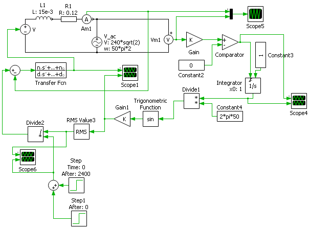
- LTSpice
LTSpice is a SPICE (Simulation Program with Integrated Circuit Emphasis) software used to simulate the characteristics of a circuit on a computer. It’s commonly used by engineers to derive mathematical models of electronic components.
The LTSpice software enables design on a circuit level. The choice of component values can be altered freely, even if the component is not on market. For example, you can choose a resistor with the value of 123456 Ω even though the component doesn’t exist in the current market.
Despite this, LTSpice’s library of chipsets and modules is not very complete yet. Thus, the software is suitable during the first stages of your design when you’re designing circuits for PCBs.
-
Fritzing
Fritzing is suitable for simpler, direct tasks since it’s more integrated and generalized. The design of the application is user-friendly, so it’s a great choice for designers who don’t have a strong background in engineering. Fritzing is however not free, it costs €8 to download and use.
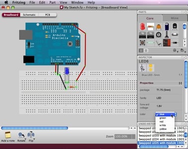
source: Fritzing
-
CircuitMaker
Similar to LTSpice, CircuitMaker is a SPICE software. Altium designed this free software to support not only circuit simulations but also PCB designs. CircuitMaker has a massive component library, with an online community to network and assist you in developing your own projects. However, up until now, CircuitMaker is only downloadable for 1 OS, Windows.
PCB Design Software
After testing and verifying your circuit design, you can move forward with:
- Designing your schematics. You should choose what components or combinations of components to use for your circuit. This will include adding test nodes, selecting input/output ports, looking into datasheets, etc.
- Designing your PCB. After you’re finished with your schematics, you should move your design to your PCB. Your PCB design should consider the impedance, volume taken, and cost of creating the circuit board.
To do the following tasks, you can use EDA software like Allegro, Altium Designer, Mentor series, EAGLE, ZUKEN, and KiCAD. The files generated from EDA software vary depending on which software to use. We highly recommend using Allegro and Altium Designer for your PCB design.
Make sure you understand the measurement requirements for manufacturing and assembling your PCB. Pay attention to your Stackup design, holes and vias, package types, and impedance control. You can learn more about these from our Knowledge Base.
-
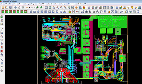
Cadence Allegro PCB Designer
The Allegro PCB Designer not only supports the layout of PCB but also provides impedance control, routing, simulation, footprint generation and placement, up until multi-layer PCB design. However, these many features might not always be accessible by everyone since their operation is not very user-friendly. Additional training might be needed before handling your project with Allegro, but once you’ve got your hands on it, you’ll be able to create complex PCB designs in just a short time.
-
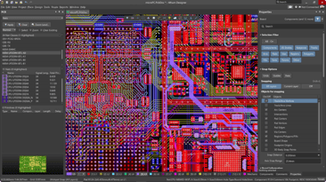
Altium Designer
Altium Designer, a paid version of CircuitMaker with more features and extended libraries is a common software for PCB designers. Even though both Allegro and Altium are used for similar functions, the annual license price of Altium is around 3 times the price of Allegro’s. Despite the higher price, most Altium users still stay loyal to the software, due to these reasons:
- Altium creates just a single footprint file for a given library, whilst Allegro creates a file for each and every pad and component involved.
- Altium provides a color picker for every unit, whilst Allegro only enables a color picker for every net.
- Altium has a better 3D viewer feature than Allegro.
- Creating BOM with Altium is faster, with its ActiveBOM feature.
Mechanical CAD Software
Other than the circuits and electrical structures of a PCB, you should also design the mechanical parts of what makes a PCB: its shape, connectors, choice of materials, etc. This could be done in CAD software like AutoCAD or Solidworks.
CAD software is used to design the mechanical parts of your IoT projects. AutoCAD or Solidworks will provide services such as structural part-by-part design, assembly, choosing materials, tolerances, clearances, and engineering drawings needed during the manufacturing and assembly processes. You’ll need CAD software to design your prototype casing too.
-
AutoCAD
AutoCAD is the most widely used CAD software. AutoCAD Electrical, a feature of the software, is mostly used to design mechanical drafts for PCBs. PCB Layouts are usually not designed here due to the limited functions. Some of the mechanical properties to be designed with AutoCAD include:
- The PCB outline.
- The position and size of internal grooves or cuts.
- Tolerance and clearance requirements.
- Some customized panel information, such as drilling patterns, hole position information, layer stacking, positioning holes, special production requirements, etc.
-
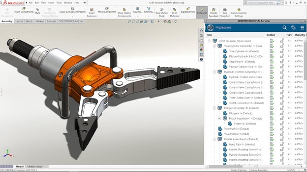
Solidworks
Solidworks is commonly used by mechanical engineers to design parts and assemblies that require a certain level of machining or 3D printing. Some initial training should be taken before handling the software since it’s not very user-friendly. Once you grasp the basics, you would be able to design small, simple parts, up until creating complex, multipart assemblies. The software is however not free and requires a license to operate in. An alternative for Solidworks would be FreeCAD, which provides similar basic features to Solidworks.
.png)
.png)
.png)
.png)