In a previous article, we discussed a bit on rib design and the reasons that you'd want to have this type of design in your plastics. In this article, we will go into more details about designing these structures for stronger plastic parts.
1. The Reinforcing Rib structure design on the plastic
The effect of Reinforcing Rib can not only improve the strength and stiffness of plastic products, reduce the distortion phenomenon, but also make plastic molding easy to fill the cavity. As is shown below.
1.1. The design principle of the Reinforcing Rib
1- The thickness of Reinforcing Rib should be less than the wall thickness of the strengthened product to prevent the joint from sag
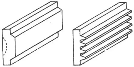
2- The height of Reinforcing Rib should not be too high, otherwise the Reinforcing Rib will be damaged, reduce their rigidity. The ratio relation of Reinforcing Rib size is shown in the picture below. To increase the stiffness of the product, the number of Reinforcing Rib should be increased rather than the height.
3- Reinforcing Rib of the slope can be bigger, generally should be greater than 1.5 °, avoid injury and demolding.
4- Multiple Reinforcing Ribs should be properly distReinforcing Ributed and arranged in a staggered manner to reduce contraction imbalance.
5- Generally, the Reinforcing Ribs are reinforced with oblique bones to avoid air entrapment, which is conducive to injection molding and strength.
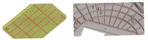
1.2. Reinforcing Rib design form
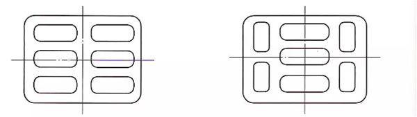
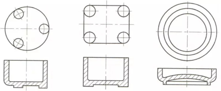
1- The Reinforcing Ribs are as long as the rectangular grid, Reinforcing Ribs are shown on the left, and as round grid reinforcing bars are shown on the right.
2- Stiffeners are designed in the corner of the box, as shown on the left, and stiffeners are set on the side wall, as shown on the right.
3- In order to increase the stiffness of the product, the number of Reinforcing Ribs should be increased instead of the height. The reinforcing bars should be designed to be shorter and more, as shown in the figure.
4- The Reinforcing Ribs are designed in a reasonable arrangement, as shown in the figure.
 Bad Good
 Bad Good
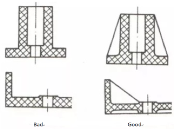
Stiffeners are designed for the vertical column, as shown in the figure.
 Bad Good
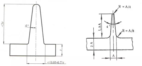
1.3. The size design of Reinforcing Rib
The size design of Reinforcing Rib should be referenced as below relation, as shown in the figure below.

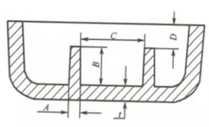
Specification:
- The thickness of the large end of the Reinforcing Rib, the value range is between 0.4t and 0.6t, generally 50% of the material thickness.
- The height of Reinforcing Rib is generally no more than 3t.
- The distance between two Reinforcing Ribs is generally not less than 4t.
- The distance of Reinforcing Rib from the surface of the part is generally not less than 1mm.
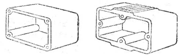
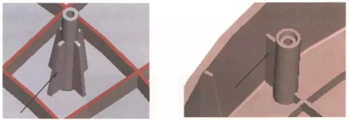
1.4. The Reinforcing Rib of screw column
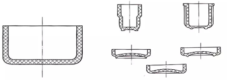
If the screw column is too high or needs to bear a certain strength, it needs to design Reinforcing Ribs to increase its strength. As shown on the left, Reinforcing Ribs are far from the side wall screw column, and as shown on the right, Reinforcing Ribs are close to the side wall screw column.
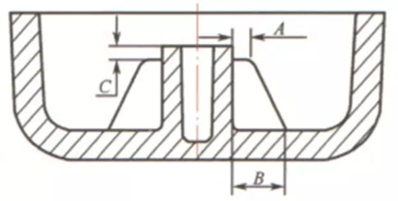
1.5. The size design of screw column Reinforcing Rib
The size design of screw column Reinforcing Rib is better if according to below picture way.
Specification:
- The plane width of the upper end of the Reinforcing Rib should not be less than 0.5mm.
- The width of the bottom end of the Reinforcing Rib ranges from 0.20 to 0.50 times the height of the screw column.
- The distance of Reinforcing Rib from the end plane of the screw column should not be less than 1mm.
1.6.The Reinforcing Rib structure design of supporting plane
When Reinforcing Ribs are made on the supporting surface, they should be lower than the supporting surface to ensure that the supporting surface is even. As shown in the figure, reinforcing bars and supporting surface are at least 0.5mm lower than supporting surface.
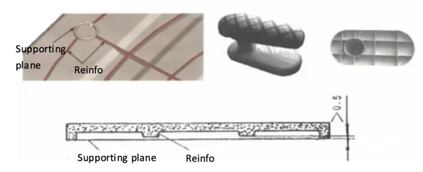
The supporting surface is the bottom surface that bears the weight of the product. For the products of larger size, if the entire supporting surface is used as the supporting surface, it is not conducive to the leveling of the bottom. Therefore, some convex edges, tables, and convex points should be designed to support the product.
2. The supporting design of a plastic product
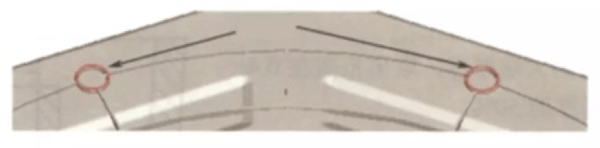
The height of the supporting surface should be determined according to the external dimension of the product, with a certain value range of 0.3 ~ 2mm.
The supporting surface shall adopt the convex platform structure, 3 of which are good, the height shall be higher than 0. 5mm above the plane, and the position shall be uniformly set in the corner of the product, with sufficient strength, a suitable slant of demolding and transition connection. As shown in figure
It is not appropriate to choose the integral plane structure for the bottom supporting surface of plastic products, because it is very difficult to make the integral plane absolutely straight. Therefore, the effect of adopting internal concave structure is better, and the concave depth should be greater than 0.5-1mm. As shown in the figure.
3. The hole design of a plastic product
Holes are often encountered in the design of product structure. There are two kinds of common holes, one is a round hole, the other is a non-circular hole. When designing the position of the hole, the difficulty of mold processing should be reduced as far as possible without affecting the strength of the plastic parts.
3.1. Common hole design requirements
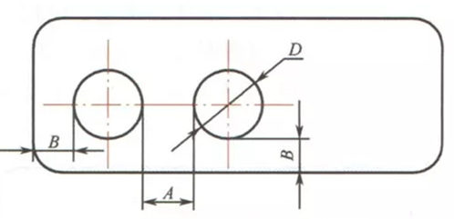
Specification of dimensions (not including inner holes of screw posts): as shown in the figure.
- For the distance between holes, if the aperture is less than 3.00mm, it is recommended that A value is not less than D. If the aperture exceeds 3.00mm, the A value can be 0.70 times the aperture.
- It is recommended that the distance between hole and edge is not less than D.
3.2. The relation between aperture and depth
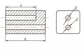
Specification of dimensions (not including inner holes of screw posts): as shown in the figure.
- The depth of the blind hole is not more than 5D. Generally, A is less than 2D and the length-diameter ratio is not more than 4mm.
If D is less than or equal to 1.5mm, then A is less than or equal to D. The thickness of the bottom wall of the blind hole should be greater than or equal to 1/6D. - It is recommended that the depth of the through-hole is no more than 10D.
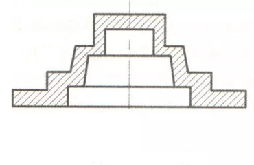
3.3. Stepped hole structure
A stepped hole is a hole with several different diameters connected on the same axis. The depth of the hole is longer than that of a single diameter hole. As shown in the figure.
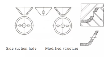
3.4. Inclined hole
The axial direction of the hole is the same as that of the mold opening, which can avoid core pulling. For the forming method of an inclined hole and complex shape hole, the split type core can be used to complete, so as to avoid side core-pulling structure. As shown in the figure, the side hole as shown in FIG. (a) is improved to the hole along the direction of demolding as shown in FIG. (b).
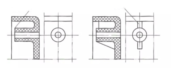
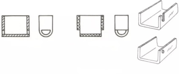
3.5. Side hole
When the side hole and side concave appear on the plastic products, the sliding block or side core-pulling structure must be set in order to facilitate the mold drawing. As a result, the mold structure is complicated, the cost increases, and the product structure can be improved. As shown in the figure, the lateral hole shown in FIG. (a) is changed to the lateral concave shown in FIG. (b).
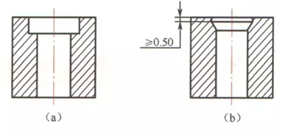
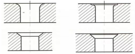
3.6. Design of screw head hole
As shown in the figure, the screw head hole shall choose the form as shown in FIG. (a) first. If the structure needs to choose the form as shown in FIG. (b), the conical surface shall be lower than the end surface and not less than 0.5mm to avoid the whole surface cracking.
3.7. Edge structure of a hole
It is not reasonable to design a complete chamfer or rounded Angle at the edge of the hole. At least 0.4mm straight body structure should be reserved at the edge of the hole. See figure.
3.8. Draft angle
Demoulding slope should be set when the hole's length-diameter ratio is greater than 2. The draft angle that we always choose is more between 0.5°to 1°, and you can design different draft angel according to your requirement.
.png)
.png)
.png)
.png)