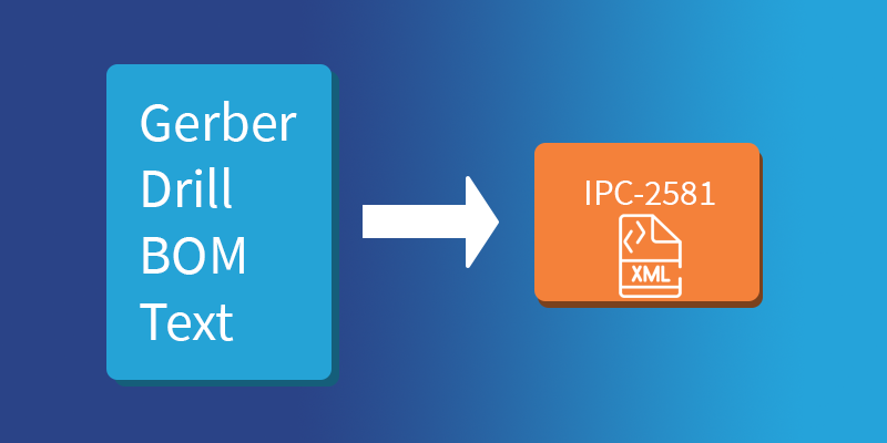
Today we will talk about some steps to export the IPC-2581 manufacturing file with Altium Designer 21 EDA and perform some simple checks.

Exporting IPC-2581 from Altium Designer
Assuming that you have completed the design of the PCB and checked the design rule, you only need to follow these steps to output IPC-2591 XML files:
- Select File-Fabrication Outputs-IPC-2581

- If this is the first time you are outputting the file, there may be a pop-up box for the file output destination, allowing you to select a folder to save the file in. Or you can directly select the default location, (usually C:\Users\Public\Documents\Altium)
- The pop-up configuration settings only have the following options, and you need to confirm the version A or B of IPC2581 as well as its units and decimal points. Generally, you should select B, and leave the other settings as default. Then click OK to generate the output file.

That’s as simple as it gets!
Checking Output Content
1. Checking file
- Open the file explorer and navigate to the custom or default output folder based on which one you chose earlier. You should see a folder that’s named after your project
(In my example below, the project name was Kame_FMU)


- Open the output folder for the project and you will see a unique output file titled XXX.CVG and an accompanying Status Report.txt You should check Status Report.txt for error messages. I prefer using Visual Studio Code to open XML files, but even Notepad will do.

2. CAD Checking
Although the XML file can be well organized and read, it is not intuitive to read because the information such as copper layer and stacking is in image format. So we also need to use CAD viewing software to check if there are any errors. Here we are using Vu2581 as our go-to software. It is a free IPC-2581 Viewer.
What is Vu2581?
To improve the IPC-2581 file format, DownStream has created a free IPC file viewer. Vu2581 is a free application designed to view IP-2581 data files. Vu2581 will read any IPC-2581 file and provide more functions than traditional viewer applications. Its unique features include measuring distance between objects, setting colors and visibility for nets, pads, and layers; setting highlight colors for one or more components; and displaying information such as drill hole size and layer thickness.
IPC-2581 integrates all kinds of information about a PCB
Before using the tool, we need to review what the IPC-2581 XML file contains, generally including:
- Image of copper layer for etching PCB layer
- Board stack up design (including rigid and flexible parts)
- Netlist for bare broad and circuit testing
- Parts list for purchasing and assembling materials (pick-and-place)
- Manufacturing and assembly notes and parameters
So we should be able to see such information in the tool and check if it is complete, so as to make sure there are no more obvious errors.
Using Vu2581
Double-click the Vu2581.exe to execute the file, click the Open icon, and select the XXX.CVG file from the folder we previously targeted.
If you get any error pop-ups, check and identify the causes carefully. Of course, errors can be caused by the software. In that case, check if you have missing layers, pads, etc.

From the tabs in the lower-left corner of the image above, you can select different tabs to check their contents.
- Layers - used to display information about the layers. You can see how many layers are there, and select to check different layers, as well as choose to display different features such as pins, vias, and copper layers.
- Netlist - You can check whether it is displayed or not. Select one or more of these nets, which will be highlighted correspondingly on the diagram.
- Drills - Drilling information. You can check whether it is displayed. Drillings of the same specifications are categorized. This is similar to Gerber's drilling table.
- Pads and Vias - Information on pads and vias. You can check whether it is displayed or not.
- Components - BOM list, including bit number, name, assembly method, height, and other information.
- Part Decals - Device stickers, for some additional information on assembly.
In a nutshell:
After exporting your design within Altium Designer and confirming the file output, you should check the output contents using Vu2581. You should then send the entire folder contents to the PCB manufacturing partner.
Switching to IPC2581 definitely helped us a ton in terms of keeping file integrity and avoiding mistakes. Working with the IPC2581 format also says a lot about the mindset of the engineer behind the project. Do you think IPC2581 should replace the legacy file formats, or are you comfortable with the old standard? Let us know in the comments!


